I have just spent a few days working with an alternator removed from a Townace (said to be 1991) which intermittently has all its dashboard lights on and isn't charging its battery. Removing the alternator was probably a mistake but it gave me a chance to investigate the alternator, read the section of the RM025E manual, research in the archives and make a few phone calls.
Any discussion of the alternator will include the vacuum pump and the voltage regulator. In essence the rotating part of the alternator is an electromagnet which, as it spins, induces alternating current into several fixed windings whose output is rectified to produce a DC supply.
Vacuum provides storable energy for the brake servo and other systems. It can be derived from the reduced pressure in the inlet manifold except when this is pressurised, for example in a turbo-diesel, when a dedicated vacuum pump is required. On Townaces that pump is attached to the alternator.
The voltage regulator controls the power output of the alternator, which is used to supply electrical systems directly and to re-charge the battery. It is more than just a "valve" that lets some power out from the alternator. It senses the electrical system voltage (should be about 14V with the alternator running) and controls what the alternator produces in the first place, by controlling the "Field" excitation current fed from the rest of the electrical system into the rotor of the alternator via the brushes and slip rings.
An additional function is to drive the "charging" dashboard warning light - though this rarely illuminates on its own. It is common to get "three lights" on or to get "all lights" on but I don't know if the difference can help diagnose the fault. Another function, on diesels, is to signal to the Glow Plug Timer that the engine has started running, so reducing the glow plug voltage and commencing the after-glow timing period.
Warning lights and failure to re-charge the battery can be caused by a number of things. From the archives the easy/cheap things to check seem to be: belt slip, alternator brushes, failed Charge fuse, bad connection of thin wires at or near battery, bad connection at or failure of fusible link. After that you have to try replacing the regulator and, if it doesn't have an internal regulator, the alternator itself.
Variations in the alternator etc appear to be as follows: (references are to pages in RM025E)
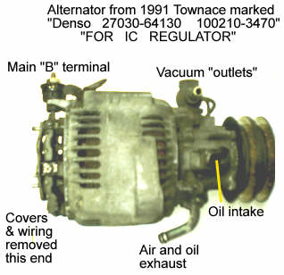
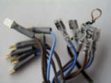
This is the alternator on which this page is based. I think it is commonly found in Townaces. There are other pictures in this folder.
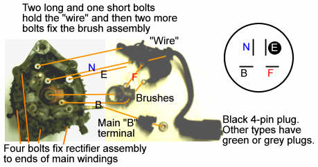
So far as I can tell the internal wiring arrangement is as below. I did not find the letters B, F, E, P marked on the alternator but they are the letters usually used to denote the apparent functions of the four terminals. One side of the rotor "Field" winding is common with the +ve rather than with Earth but note that, unusually, there appear to be four, not three, main windings. There is some consistency with the drawings on CH-3.
Doing no more than disconnecting the plug and measuring about 3 ohms between F and B while turning the engine/alternator a little by hand should verify the state of the brushes and rotor winding.
I have not verified this, but the procedure starting at CH-5,7(a) [w/IC Regulator] should help with diagnosis if inspection has revealed nothing amiss. Even though the two drawings at the bottom of CH-6 don't help you expose the "F" terminal, use the procedure "With the engine running ... connect terminal F to body ground" (which with the type of alternator I examined puts the full battery voltage across the rotor Field winding, regardless of the regulator. That's OK). This should energise the alternator and cause the output voltage to rise, making lights noticeably brighter. If so, suspect that the regulator was failing to energise the alternator. If not suspect a fault in the alternator, which may just be brushes.
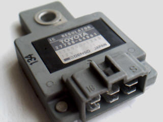 The external IC regulator can be found by emptying the glove box and pulling it right down - squeeze the right-hand side in hard so that the plastic "stop" goes past the dashboard, then do the same on the left-hand side. Look into the right side of the space behind where the glove box was. Remove the securing bolt with a 10mm socket, pull the regulator up and dislodge the loom connector.
To do tests on the alternator/regulator you need to make up a set of cables with 1/4in connectors, six male and six female, joined via a screw terminal block. Be careful, some of them are permanently "live" and only protected by very high current fuses.