Meter connectionsRemoving the instrument panel is straightforward and described in the editorial in the Dashboard & Electrics folder of this Ace Answers website. Here is the arrangement of the three connections to the temperature indicator, as you see them at the back of the panel. The 1Watt 47ohm resistor is fitted as a shunt between the TU (temp. unit) sender terminal and the earth terminal. You can fit it in 20 minutes without even leaving the driving seat! | 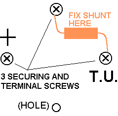 |
|
Standard Overall responseIf your gauge usually sits about three graduations below the centre (at "7" on this scale although you'd be pretty observant to know whether it was 6, 7, or 8) then this explains why. The measurements and formulae on which it is based are described below. | 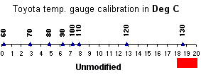 | ModificationAdd a resistor as shown above. The immediate effect is that pointer will go to "7" as soon as you turn the key even when the engine is in fact cold. So the downside is that the lower third of the scale will no longer show you the engine warming up. The benefit is that choosing the value of the resistor now allows you to choose the temperature range over which you want the indicator to be sensitive. 47ohms is probably the best, starting at 80C. 39ohms (these are the standard resistor values) might be of interest - covering lower temperatures but the scale is more cramped. 56ohms and 33ohms are shown for illustration.The resistor must be rated for at least 1 Watt. Get a wirewound type with a temperature coefficient less than 300ppm/C if you can, it should cost less than a pound from any electronics shop. (Email me if you're stuck and I'll send you one). | 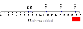 | 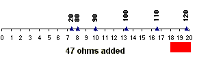 | 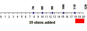 | 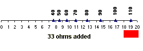 |
|
Wiring detailFor reference, this schematic shows the arrangment of the sender and indicator. Pin numbers refer to the blue connector, see below. | 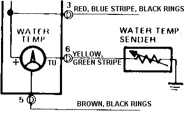 |
|
Connector pinsThere are 3 connectors to remove to get the instrument panel out. This one is the only blue one. I had to identify the temperature gauge wire, on pin 6, in order to break it. | 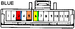 |
|
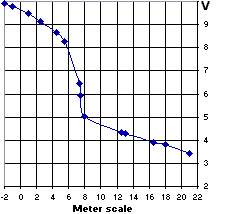
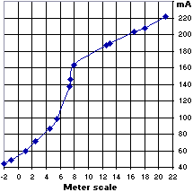
Test arrangementFor the record, in case you want to see if my results are repeatable, this was my test setup using two digital multimeters. In all I brought 5 wires out, as shown, for test purposes. Below are the results which I obtained. I revved the engine for each reading, to bring the supply Volts up to normal | 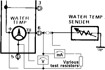 |
|
|
Indicator characteristicHere is the most useful way to show the results of the test. The ohms load is calculated from the Volts and mA data above. Amazingly, it has two straight lines and so can easily be modelled by two formulae to derive the calibrations above. | 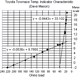 |
|
Sender characteristicI'm grateful to David Miller who supplied the measurements which he made, plus two (50C and 115C) from the Toyota test spec. These all fit very closely to a normal logarithmic thermistor characteristic, as shown by a trend line whose formula is given and used to derive the calibrations above. | 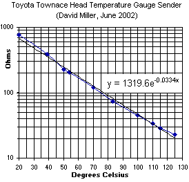 |
|