Temperature Gauge replacement - John Davis
Pictures & diagrams ...
Temperature gauge replacement - John Davis
Ref sourcing the Durite or Tim type sender to the 2C-T engine, you might like to have a look at
Vehicle Wiring Products whose online catalogue lists both of these in it's "gauges" section. If you fit the TIM gauge (Part No TO34) I see that various adapators are included. If you fit the Durite gauge, (Part No 52323) you will need the 16mm x 1.4 adaptor, part No T262.
1. The existing sender is mounted in the cylinder head, on the inlet manifold side of the engine. You will see, just above the starter, one sender but, this is to supply a feed back to the glow plug timer and, anyway, it is screwed into the BLOCK Slightly above it, screwed into the HEAD is the engine coolant temp sender.
2. Is it hard to get out ? It's not that easy but, when I did mine, I removed the starter (easy job) and this makes all the difference for access. I found that a ring spanner was better than a socket. If you screw the new sender into the adaptor first, and then screw this assembly into the head drilling, is is likely to be less fiddly than trying to fit the sender into the adaptor afterwards. The sender/adaptor, screwed into the head, (into the waterways) is the electrical earth return for the sender's circuit so, if you joint this thread (PTFE tape or liquid sealer for instance) do make sure that there is a good earth connection here. You might find that the existing sender, can be removed via the engine bay, ie, passenger seat up. However, I found that working from below, with the starter off, was the best way for me.
3. Wiring route. Because I had the drivers seat out together with the floor pan, for other jobs which I was attending to, I ran the feed wire (standard Halfords auto wire) under the folded edge lip of the floor pan recess. I drilled a few holes and fitted mini type cable ties.I routed it right around the engine bay, emerging under the carpet, by the throttle pedal, and up to the gauge location. I attach a couple of views of the gauge and you can see where I have taken the cables, ie, sender, earth, power feed via ignition switch, power feed for the internal light in the gauge etc. If the floor pan had not been up, I should have just run the cable, under the carpet, around the engine bay.
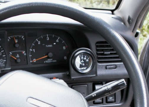 4. David Miller has managed to replace the internals of the Toyota gauge with those from the Durite, probably not difficult for him. However, I am very happy with the mounting which I have chosen (see picture). The gauge sits in a piece of 1-3/4 plastic drain pipe, sprayed matt black, all of which is clamped into one of the Durite mounting brackets, part No 24301 (Cost 53p ! ! !). This assembly sits halfway into the speedo/instrument recess. From the drivers position, it does not shield any of the warning lights, nor does it hide any of the rev counter dial, nor does it interfere with the ignition switch or any other device. Altogether, I feel that it works well in this location and, with the (almost) hidden wiring, does not look out of place at all.
I hope that these observations are helpful to you but, as I have said in a BOK posting, all I have done is copy what David has done. He has, as usual, been extremely helpful with his postings and direct emails and I feel that the result, with my vehicle, is a great improvement.
- John Davis, 27 Aug 2002.