Traction Voltage is supplied to track districts as follows.
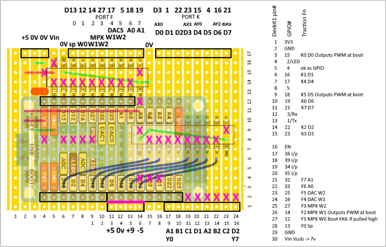
ReplacingArduino MEGA2560 AND DACS with ESP32 Devkit1, buffered:
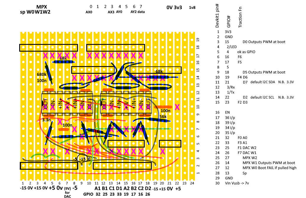
ReplacingArduino MEGA2560 with ESP32 Devkit1, buffered:
Bill of materials for Traction Stack (excluding throttles). Prices here include VAT.
| Part | Cost each | Quantity | Total cost |
| Quad DAC IC | £5.66 | 2 | £11.32 |
| MEGA 2560 | £7.21 | 1 | £7.21 |
| Caps, Res | ~£0.05 | 28 | £1.40 |
| Regulators | ~£0.35 | 3 | £1.05 |
| Padboard | ~£0.45 | 1 | £0.45 |
| Connectors | ~£0.10 | 4 | £0.40 |
| LEDs | £0.11 | 2 | £0.22 |
| Mpx IC | £1.83 | 2 | £3.66 |
| Connectors | ~£0.10 | 14 | £1.40 |
| JLC/PCB | ~£0.60 | 2 | £1.20 |
| LEDs | £0.11 | 4 | £0.44 |
| Total: | £28.75 | ||
The TLC7226CN quad DAC ICs were hard to source and comprise almost half the cost of the traction stack. I decided to get two at £4.72 +VAT each from Digi-Key for layout 2, with Arduino Nano, because they made the D-to-A conversion much more predictable than using PWM. Later I may try instead the elegance of using PWM straight from an Arduino via a simple filter. The DAC board has been re-used in layout 3 with the Arduino connections altered slightly to better suit the Arduino MEGA port layout.
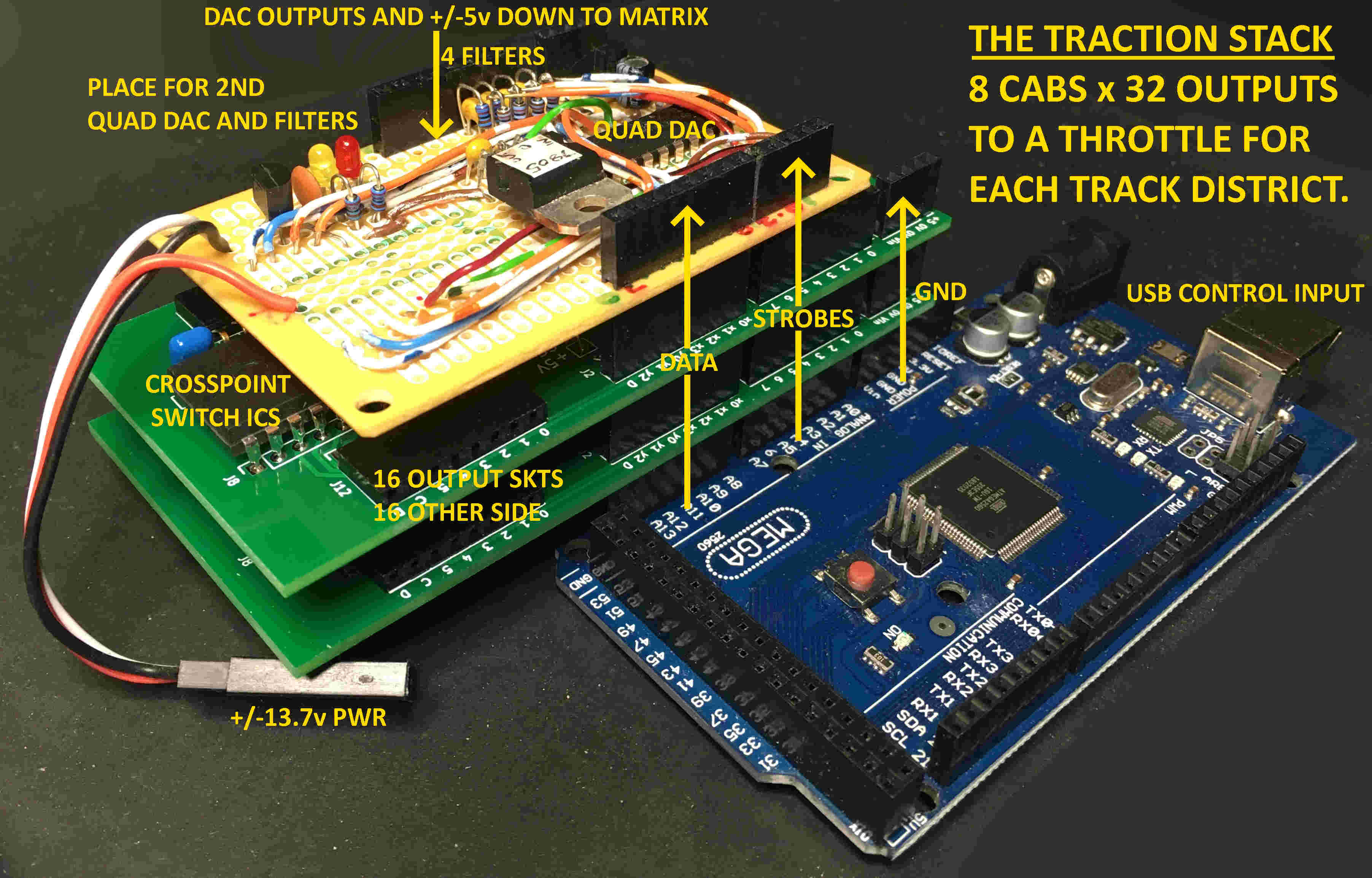
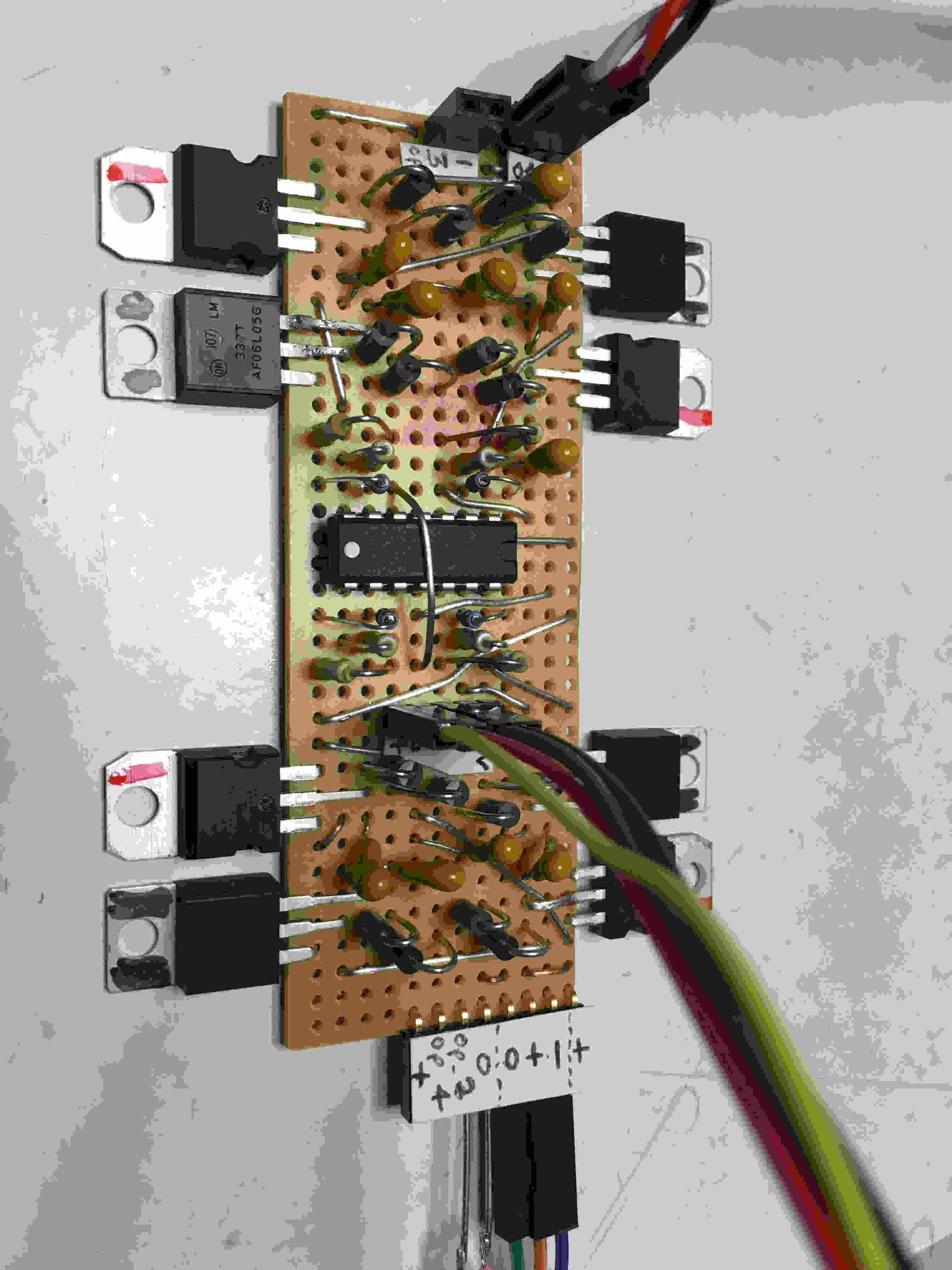
To deliver +/-5V ouput the DACs need +9V Vdd supply, +5V reference, -5V Vss/analogue "ground" and ~13.7V bias to pull the outputs down to -5V under load. So I supply +/-13.7V to the board and use 3 regulators to derive the +9V and +/-5V. The +/-5V is needed by the MT8816AE CMOS crosspoint matrices as well, which will be on PCBs stacked with the Arduino MEGA and DACs.
Each MT8816AE1 IC is an 8 x 16 array of analogue crosspoint switches. These can handle +/-5V signals and be controlled by an 8-bit data bus (the same bus that controls the DACs) and a Strobe/Write line for each IC. A PCB for each (of two) MT8816AE ICs stack directly onto the Arduino Mega, and the stripboard with the DACs stacks on top of those. Power, data and Write lines will be fed through the stack.
Datsheets for MT8816AE1 give the pinout used in the PCB design for the 16 pins used here as outputs. Tests give a different result with pins 0-7 along one side and along the other side: E, F, 8, 9, A, B, C, D. There seemed little point mapping, in the Arduino, to re-produce the irregular arrangement on the datasheet (& PCB labelling), so the outputs are mapped to put simply 0-7 on one side and 8-F on the other side. This makes wiring more convenient but the PCB labelling is misleading. A0 script/sketch comments have more detail.
Having decided to pursue the idea of the cab/district matrix being CMOS upstream of the throttles, I need one throttle per track district. Possibly 32 throttles, each with one robust output that can swing from around -10V to +10V.
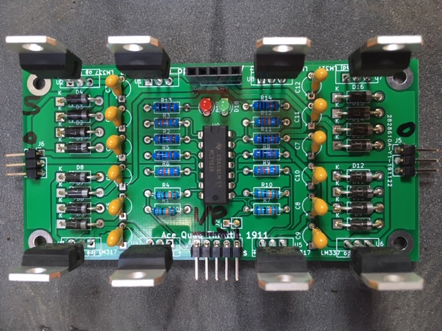
For a low-part-count, low-cost solution I ended up successfully trying using complementary programmable Voltage regulators (LM317/337) with in built current limiting and over-temperature protection. These behave like emitter-followers except the output is 1.25V more than the ("Adjust") input. Four diodes at the output hold off about 2.8V so prevent the regulators "fighting" each other - the slight glitch as the output changes polarity is acceptable in a traction supply. Capacitors (1uF) are needed to stablise the outputs and because the output can swing both +ve and -ve these must be returned to the opposite supply rail, rather than to 0V, to be able to use electrolytics, and they must be rated for twice the supply Voltage.
Op amps are included partly to ensure that the output goes to 0V when an input is open-circuited. Input bias resistor is 680k, not 390k.
Gain is needed to get +/-10V out because the DACs and CMOS matrix can't handle that. Feedback resistor is 12k, not 10k.
LED loads are ~10k.
Bill of materials for quad throttle. Prices here are for quantity and include VAT.
| Part | Cost each | Quantity | Total cost |
| LM317 | £0.30 | 4 | £1.20 |
| LM337 | £0.45 | 4 | £1.80 |
| 1uF 35V | £0.12 | 12 | £1.44 |
| 1N4001 | £0.02 | 16 | £0.32 |
| TL064 | £0.47 | 1 | £0.47 |
| LEDs | £0.11 | 2 | £0.22 |
| Connectors | ~£0.10 | 4 | £0.40 |
| Resistors | ~£0.02 | 12 | £0.24 |
| JLC/PCB | ~£0.40 | 1 | £0.40 |
| Total for four throttles: | £6.49 | ||
| (Will be less than £5 if LM317/337 are bought on long lead time from China.) | |||
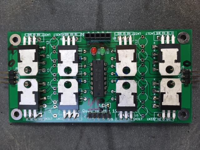
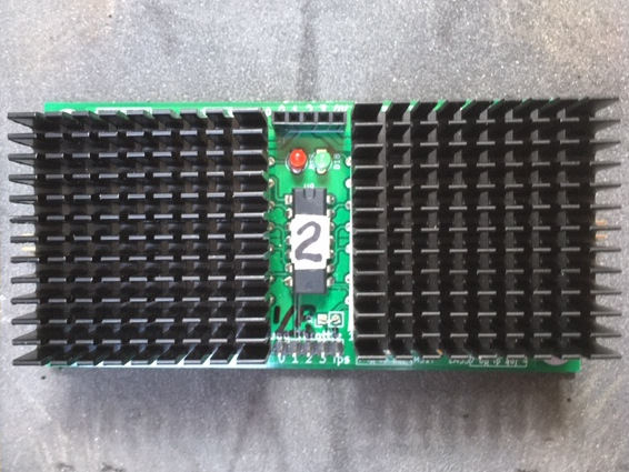
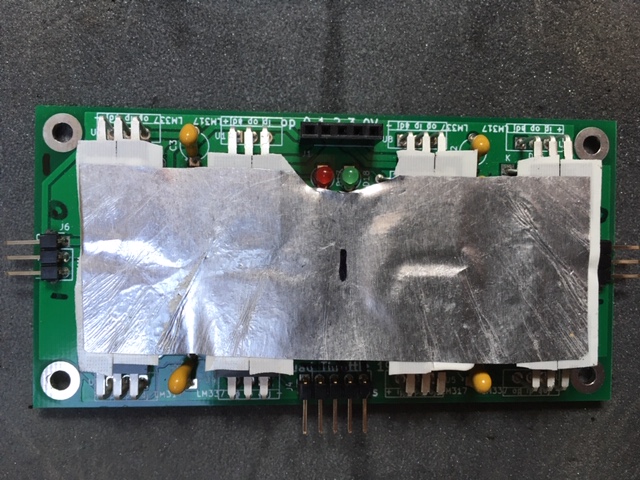
Initial tests verify the stability and robustness (surviving heavy load and short circuits) of this design. At modest speed (N gauge) the regulators get hot but heat sinks are probably not necessary or could just be a piece of foil fixed with double-sided thermally-conducting tape.
10 bare 100x50mm PCBs were my first ever PCB design. Thick aluminium foil seems adequate as a heat sink for N gauge current, either type fixed with double-sided thermally-conducting adhesive tape. Oops! Right angle header connectors obscure my pin labels.
|
|
|
 |
|
|
This, first automated time trial (26 Nov 2019) verified the reliability of the Hall effect sensors and control system as well as the Traction system. The loco repeatedly traversed the measured distance, stopped and reversed. The trial started fast and gradually slowed, so the loco was "warmed up" but as the speed fell to around 2mph it probably cooled down. Also progress took a long time - a good job it was automated. Some issues with the USB had to be fixed but the loco only stalled once - which marked the end of the trial.
The pulses were around 5ms wide, 6V high at 27Hz. It will be interesting to compare a result with smaller, or no, pulses. Also trying to keep the loco at constant temperature - interspersing slow and fast runs.
The overall slope is around 17mph per Volt. Below 4mph this reduces by a factor of two. This explains why increasing the Voltage at a constant rate produces unrealistic acceleration. The model loco creeps away then gathers speed more quickly instead of the other way round. Compare theory on right. It will be possible to derive a better nominal Volts/time characteristic.
HP lower LH USB skt. 5.11-5.14V 0.00A
Start Picoscope in HP lower LH USB skt: 5.07-5.10V 0.33A
Black 4-way USB hub in HP lower LH USB skt. 5.11-5.14V 0.00A
Add and start Picoscope: 4.88-4.92V 0.32-0.35A
Black 4-way USB hub HP lower LH USB skt IS COMPATIBLE with Picoscope.
Start Picoscope in HP RH USB skt: 5.04-5.07V 0.33A but used for mouse.
HP upper LH USB skt. 5.09-5.12V 0.00A
Traction MEGA2560 in HP upper LH USB skt: COM5, 4.99-5.10V 0.07A
DAC board alone on 13.7VPSU: 0.17A
Traction MEGA2560 in HP upper LH USB skt: 0.07A, & DAC board: 0.15-0.19A
Add Picoscope in HP lower LH USB skt: MEGA "5V": 4.90V, DAC "5V": 5.08V
Join MEGA "5V" to DAC "5V": now 5.00V, MEGA: still 0.07A, DAC board: still 0.15-0.19A
DAC 0-7 all ok 28.2Hz meas. (0g25+0f5b) and 0fa0 54.2Hz nom. 50.4Hz meas.
To identify cab by frequency...
0f10->6Hz, 1f30->16, 2f50->27, 3f70->38, 4f90->48, 5g40+5fa0->54, 6g40+6fc0->65, 7g40+7fe0->75
Traction MEGA2560 in HP upper LH USB skt: COM5, 4.74-4.78V 0.08-0.10A with DAC board & 3x MPX unpowered
with DAC board & 3x MPX on 13.7VPSU: 0.19A, MEGA2560 drops to 0.07A.
Re-open A0/COM5 Serial monitor. Set cab freqs (& widths). (Check Tools/Board is MEGA)
Cabs appear shorted to each other. MPX#1 error -needs two links CS & RESET.
Test MPX#2 only (previously used as W1 on F2). 4,6-F always connected. 0-5 as 0,7,5,B,?,8 !
Test MPX#0 only (previously used as W2 on F3). Works as expected.
restore in write_to_MPX() 2 x delayMicroseconds(12); and improve PORTF defaulting.
Test MPX#1 only (new). Works as expected.
Test MPX#2 only (again, with delay_us). STILL SAME FAULT. U/S.
Test Throttles.
+/-2V 100Hz triangle in, X-Y plot +/-5V ranges: ~0.1A, check ch 0-3 with around 15ohm load
#0 (prototype) not yet tested
#1 ch3 slightly unstable -ve under load
#2 w/h/sinks. Mis-powered. All ok 210417
#3 ch0,1,3 slightly unstable -ve under load
#4 w/h/sinks. All ok 210417
#5 ch0,1,3 slightly unstable -ve under load
#6 ch1 slightly unstable -ve under load
#7 all ok
#8 ch3 slightly unstable -ve under load. Mis-powered.
-ve rail short to gnd. +ve rail ok
no LEDs fitted. Suspects: C4, C10, IC9
Test with only +14V, 0V=-ve. All ops same: +ve ok. -ve sends op straight to +10V
Look at opamp ops. All as above.
Remove C10 and then C4 -ve reservoir. (Difficult to put back)
Comes good, except first channel has some hysterisis under load - caps removed?
#9 ch0,3 slightly unstable -ve under load
#10 all ch slightly unstable -ve under load 210417