Dave E Mason - model railways
|
 |
|
 |
 |
 |
| Plain index |
| The online reference archive
for owners of imported Toyota MPVs.
Here you can access Question and Answer threads classified into subject archives
and a variety of links and summaries. |
|
The primary function of this website is now to hold the documentation for my model railway project. So it is work in progress - like the project. I publish it:
- so I can access it on any device, at my desk, at the bench, in the middle of the layout, out and about,
- so I can provide links when I want to point someone else to images/information contained here,
- so that friends can maintain their interest in the project.
Secondarily this website still holds an archive of discussions between owners of Toyota Townace people-carriers - which is where the website name/URL comes from.
(top)
Mental challenge of project management and problem-solving.
Dexterity challenge of building layout, electronics, scenery.
Construction to be done in the loft, but layout to be transportable.
Train movement to be realistic - good slow running, good sound effects.
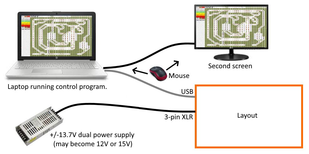
Control panel(s) to be "glass" - computer/tablet display with touch or wireless mouse input.
A simple as possible - but no simpler. I want to understand my choices.
Documentation to be mainly in this website, easy to refer to on phone/laptop.
| The layout is treated as a peripheral to the computer, rather than the computer being an add-on to the layout control system. Operation to be manual or automated in an interesting fashion to schedule/rules.
|
 |
|
NOT getting backache from working in awkward positions.
NOT acquiring a large collection of locos and rolling stock.
Starting point
(top)
Embarking on this hobby in August 2018 my first experience was with a Farish (Poole, class 25 Diesel, off eBay) loco, a borrowed H & M Duette controller and yard of N flexitrack. The Duette's half wave DC option gave surprisingly good slow running. My early experimental electronics were able to replicate this slow running and, at lower frequencies around 30Hz, to cause the motor in the loco to sound more prototypical than it did when silent.
I decided to stick with N gauge for overall compactness without trains getting to their destination too quickly.
I decided to stick with "DC" (not DCC) control, preferring layout-based sound effects to the limitations of (N-gauge) on-loco sound quality and strongly preferring to develop my own electronics rather than pay someone else to do that. Also noticing that DCC systems (e.g. McKinley) still end up splitting the track into many districts, first to facilitate fault-finding and second for train-on-track detection.
Design review October 2020
(top)
Having got trains running under automation with only half the track/bed in place, here are some lessons learned.
- The 3D design of the layout has proved sound. Gradients and clearances have turned out sufficient, as expected. However I did not stick to the plan to make the trackbed mostly of two layers of 3mm hardboard - that is apart from wide, level areas at the stations which are 5mm ply. One layer of 3mm hardboard, fluffy side up, seems adequate. It's worth noting that you can't glue a structural joint to the fluffy side, it just pulls off. The plan was to glue two layers together, smooth-to-smooth which works but then leaves you the problem of gluing the assembly to its supports. The trackbed is typically made of pieces, of various curvatures, each about 300mm long with hardboard "joiners" glued under the joins and supports at about the same intervals.
Train locating is where I changed my mind the most. Reed or Hall switches seemed cheap and reliable, placed beside the track rather than between the rails. They connect directly into the GPIO ports on the MERG CBUS CANMIO modules. I was able to fix 2mm cube magnets to opposite corners of several locos and so gain some experience with the system.
Then I started using Arduinos (Nanos) with more flexible signal processing than the CANMIOs and realised that my DC traction system, with a common 0V rail, allows very simple current detection. So now I intend my primary train location to be by detecting current drawn in the 50 or so track sub/districts. Secondary "spot" detection can be by light-dependent resistors (LDRs) placed between the tracks picking up sharp changes in ambient light at key locations. The LDRs can be pairs-in-series about 30mm apart thus ignoring gaps between coaches/wagons.
The benefits are...
- Less wiring. Current detection uses the traction wiring.
- Not having to prepare places to glue magnets to locos. They were easily knocked off.
- Continuous (current) detection rather than momentary. Switches were not completely reliable - either the contacts or the following electronics sometimes did not react quickly enough. Current detection can report the full start-of-session situation.
The traction system was intended to supply 32 track districts and provide power sources for up to 8 locos moving at any time. Even with only half the layout complete it became clear that the whole layout naturally divided into more than 32 districts. So the matrix will (easily) be increased to 8x48 instead of 8x32.
The 48 "power supply" districts are only part of the story. Some track "sub"-districts are powered via an adjacent district from which power is switched when a turnout is operated, typically a siding or a short piece of track between two turnouts. Such sub-districts could also be sections of plain track switched by a relay. These sub-districts will have their own 0V return and so provide more detail from the current-detection system.
It is possible to go a stage further. All track joints are insulated so each piece of track within a district (or sub-district) can have its own 0V return and therefore extend the discrimination of the current detection system - though requiring some extra wiring.
The MERG CBUS system offers two benefits. Only four wires are required between modules, each module connecting to up to 16 turnouts or detectors. Secondly the messaging can provide a form of automation.
My automation is with Python so the CBUS messaging automation option is not used. My layout is small and the CBUS provides little benefit in reducing the total amount of wiring. Also the CBUS CANMIO modules can not, by default, operate servos simultanously for sets of gates or doors, nor can they provide the bespoke "bounce" characteristic for my cam-operated semaphore signals.
So Arduino Nanos, on the primary USB LCB (Layout Control Bus), will process the outputs of district current-detectors (probably some via I2C 23017 expanders) and any LDRs (possibly multiplexed by CD4051s). These Nanos can also operate servos for sets of gates/doors and semaphores. Ultimately turnouts can also be operated by the Nanos, making the CANMIOs redundant but that is not necessary immediately. The Arduino-based solution has a big advantage that each servo's angular target positions is stored on the laptop rather than inside the CANMIOs which facilitates modification, fault-finding and replacement.
Glossary
(top)
Automation. Essentially, in this project, this means that trains will move around interestingly without continuous user input. The whole layout is run by "artificial intelligence" deciding on appropriate movements for trains. Then an interface for driving trains, operating turnouts, signals etc is available for a user to over-ride the automation. Automation rules are in an easily-edited text file, such as:
- When a train approaches a facing point, what percentage of the time should it divert? This can depend on the type of train and will depend on whether either next signalling block is available.
- When a train approaches a station, what percentage of the time should it slow and stop? This can depend on the type of train and will depend on whether the next signalling block is available.
- When a train is stopped in a station, how long should it wait. This could have a random variation. It can also have a dependency, for example a branch line train could wait until just after a main line train stops at the same station.
- When and where to generate sound effects, such as station announcements and horn sounds approaching a tunnel or a station where a train will not stop.
Cab. Here, the only interface available to the user is the on-screen graphical user interface (GUI) and the term "cab" is used here for the parts of the interface dedicated for controlling individual loco/trains and for data used for addressing within the traction electronics.
DAC (Digital-to-Analogue Converter/Conversion). Particularly in the traction system, the [digital] computer data has to be converted somewhere to the variable "DC" Voltage applied to the tracks. A popular way to do this is PWM (Pulse Width Modulation) where a single pulsed digital channel, followed by a filter, can, by varying the pulse shape, deliver a continuous range of output Voltages. The alternative which I favour is dedicated DACs into which 8-bit data is strobed from a bus. DACs avoid the bandwidth limitation produced by the filtering of PWM, and avoid the potential of radiation affecting other parts of the layout - or beyond.
District. This term is used here, rather than "section" or "block" for a length of track which is isolated from adjacent districts and can be fed from a different, or the same, source of power, irrespective of any relationship to signalling. "Section" has too many uses. "Block" is used more in the context of signalling.
Matrix. Means of operating many locos simultaneously and independently. The matrix connects track districts in the vicinity of a specific loco to the controlled power source for that loco. If there is a throttle/power amplifier for each loco then the natural choice is a relay matrix. However, here a CMOS matrix is used and, after that matrix, there is one throttle/power amplifier for each track district. A third option, one DAC per district, could have eliminated any hardware matrix but required careful interlocking in software.
Module. This term is used here for the parts into which the physical layout can be disassembled. Electronics is referred to as a board or node.
Numbering. (Enumeration) In software this is always zero-based (standard in Python). So this carries over to such as cab and track district numbering. MERG CANMIO channel enumeration is one-based (0x01 to 0x10) but this is translated to/from zero-based near the Python serial port - which usefully means the channel is specified in one hex character.
Reversing. Each track district is marked on the mimic diagram (by small arrows on straight sections) with a "normal" direction of travel. This even applies to single-track branch lines and "reversing" districts - some of which are (hidden) loops from the branch line and (visible) districts associated with crossovers between the main up and down lines. Normally, facing in the direction a train is moving the right-hand rail is at 0V and the left-hand rail is -ve. Reversing districts are the exception, they have two multiplexing outputs so that either rail can be driven/powered. To avoid the ambiguous term "reversing" I often refer to them as two-power-source (2p) districts.
All trains are either Diesel Multiple Units (DMU) or Diesel-hauled. Apart possibly from the class 08/20 the term "reversing" doesn't really apply to the direction a loco is facing/moving. Reversing does have a meaning for a non-DMU train and that is where it is used, meaning the loco pushes the coaches/trucks. Reversing could mean travelling in the non-normal (as in first sentence) direction for the track district but for clarity this will be described as "wrong-way" or "opposite-way" working.
Stiction. More force is needed to overcome friction to get something moving, than is needed to overcome friction to keep it moving. "Anti-stiction" pulses are supplied to locos to get them to move away from rest less jerkily. They are probably overcoming more than pure stiction. There are two associated similiar effects which pulses help with. Small DC motors get stuck because of magnetic effects. Locos can get stuck because of poor contact between wheels and rails.
Throttle. This term is used here for the device (power amplifier circuit board) which restricts the flow of energy rather than for the pedal/lever/knob with which a user interfaces to the former.
Train locator.
Report when a train passes a detector. Does not identify loco but my control software "knows" which train/cab's power is supplied to each track district. I tried a cheap solution using trackside reed switches in scenic areas and Hall effect sensors on hidden track - which require a magnet (2mm cube) on each side of each loco. Instead I intend to use light-dependent resistors (LDRs) and ambient light in just a few locations and get most feedback from Track Current Detectors (TCDs).
Turnout. This term is used here because it is less ambiguous than switch or point. However the useful term "point blades" may be used.