Operating Voltages
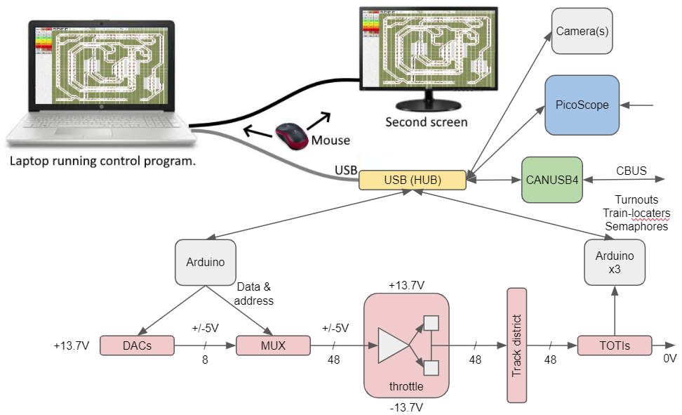
Mega2560. Vin (recommended) 7-12V. Vin (limit) 6-20V
Nano. Vin (recommended) 7-12V. Vin (limit) 6-20V
555. Vin (recommended) 16V. Vin (limit) 18V
L272 op amp. Vin (recommended) 4-24V. Vin (limit) 28V
(LM)78(L)05 to 7818 regs. Dropout 2V. Vin (limit) 35V
LM317/337 regs. Vin-Vout (recommended) 3-40V. Vin-Vout (limit) 40V
Voltmeter, 3-digit, 3-wire. Vin 4.5V to 28V
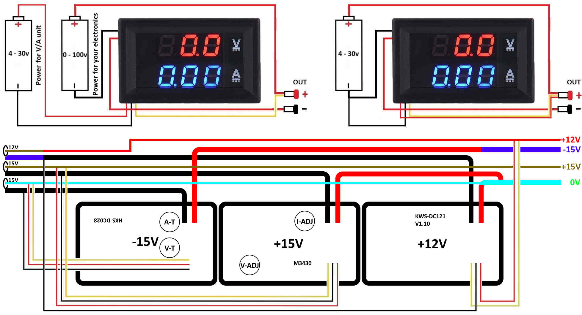
Volt + Amp meter. Vin 4V to 30V
 £2.69
£2.69
LED DC 0-100V 10A Digital Voltmeter Ammeter

    Working voltage of Meter itself:DC 4 - 30V

(The maximum input voltage can not exceed 30V. Otherwise the meter will be burned)

    Working current of Meter itself:≤20mA
    Voltage Measuring range:DC 0 - 100V
    Current Measuring range:DC 0 - 10A
    Voltage resolution (V):0.1V
    Current resolution (A):0.01A
    Measure accuracy:1% (± 1 digit)
    Display:0.28" digital tube, Two color blue and red
    Refresh rate:about 300mS / times
    Dimensions:48mm*29mm*26mm
    Operation Temp:-10℃-+65℃Wiring:
 £4.45
£4.45
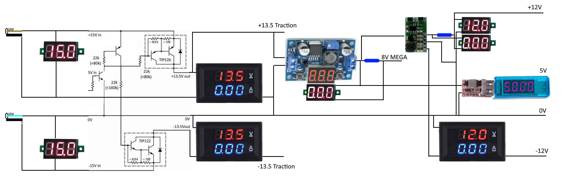
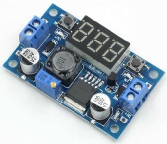
Input: 4 - 40VDC. Output: 1.25-37VDC adjustable, 2A.
Input reverse polarity protection. Output short protection. Thermal shutdown.
L x W x H =6.1*3.4*12 cm. Weight: 22g
Voltmeter range: 0 to 40V, error ±0.1V.
Press the right key to show the input or output voltage.
When the right "OUT" led lights, it shows output, the left "IN" led show input.

(1) Output voltage meter calibration steps. Voltage display resolution is 0.1V.
Step 1, Adjust right button so "OUT" LED is on, voltmeter shows output voltage;

        Press right button for more than 2 seconds, release, voltmeter and "OUT" LED
            flashes in synchronization indicating output voltage calibration mode.

Step 2, Press the right button (normal speed), the voltage value is adding up a unit;
        press the left button, minus a unit;
        Adjustment step may be less than 0.1V, depending on the current display voltage.
        You may need to continuously press 1-5 times to see the voltmeter change 0.1V.
            the higher the voltage, the fewer the number of presses needed.

Step 3, Press right button for more than 2 seconds, release, to exit calibration mode.
        All parameters set to automatically power down to save.

(2) Input voltage meter calibration steps
Step 1, Adjust right button so "IN" LED is on, voltmeter shows input voltage;

        Press right button for more than 2 seconds, release, voltmeter and "IN" LED
            flashes in synchronization indicating input voltage calibration mode.

        Steps 2 and 3, as with the output voltage calibration method.

If the module output Voltage can not be adjusted, the output voltage is always equal to the input voltage
please rotate counterclockwise the potentiometer 10 turns or more, then you can adjust the output voltage.
 £2.95
£2.95
 £2.40
£2.40
| St Blazey | Par | North | Par | Fowey |
| 13 GL Vi | 1 FR N Pi | |||
| 12 GL Pink | 25 0V | 2 FR L Vi | 14 [0V] | |
| 11 DL Vi | 24 +V | 3 RXouter Vi | 15 [+V] | |
| 10 DL Pink | 23 -V | 4 RXinner W | 16 [-V] | |
| 9 PM Vi | 22 | 5 RP N Pi | 17 | |
| 8 PM Pink | 21 | 6 RP L Vi | 18 | |
| 7 TR Vi | 20 | 7 PR N Pi | 19 | |
| 6 TR Pink | 19 | 8 PR L Vi | 20 | |
| 5 TU Vi | 18 MIO 5V | 9 | 21 | |
| 4 TU Pink | 17 CBUS +V Pi | 10 | 22 | |
| 3 SU Vi | 16 CBUS Lo Y | 11 | 23 | |
| 2 SU Pink | 15 CBUS Hi Gy/Be | 12 | 24 | |
| 1 | 14 CBUS 0V Bn | 13 | 25 | |
| North | ||||
| 13 | 1 I2C SDA Bn | |||
| 12 | 25 0V | 2 I2C Vcc Be | 14 MPX 0V | |
| 11 | 24 +V | 3 I2C GND Y | 15 MPX 08 | |
| 10 | 23 -V | 4 I2C SCL Pi | 16 MPX 09 | |
| 9 | 22 MPX 07 | 5 R 5V USB3 | 17 MPX 0A | |
| 8 | 21 MPX 06 | 6 W D- USB3 | 18 MPX 0B | |
| 7 | 20 MPX 05 | 7 Gn D+ USB3 | 19 MPX 0C | |
| 6 | 19 MPX 04 | 8 Bk 0V USB3 | 20 MPX 0D | |
| 5 R 5V USB1 | 18 MPX 03 | 9 Screen USB3 | 21 MPX 0E | |
| 4 W D- USB1 | 17 MPX 02 | 10 | 22 MPX 0F | |
| 3 Gn D+ USB1 | 16 MPX 01 | 11 RXinner W | 23 -V | |
| 2 Bk 0V USB1 | 15 MPX 00 | 12 RXouter Vi | 24 +V | |
| 1 Screen USB1 | 14 MPX 0V | 13 | 25 0V | |
| St Blazey | Par | North | Par | Fowey |
| St Blazey | Par | South | Par | Fowey |
| 13 | 1 PR N Pi | |||
| 12 | 25 | 2 PR L Vi | 14 | |
| 11 | 24 | 3 PB N Pi | 15 | |
| 10 | 23 | 4 PB L Vi | 16 | |
| 9 | 22 | 5 | 17 | |
| 8 TR Vi | 21 | 6 | 18 | |
| 7 TR Pink | 20 | 7 | 19 | |
| 6 UL Vi | 19 SU Vi | 8 | 20 | |
| 5 UL Pink | 18 SU Pink | 9 | 21 | |
| 4 LU Vi | 17 RT Vi | 10 | 22 | |
| 3 LU Pink | 16 RT Pink | 11 | 23 | |
| 2 LD Vi | 15 PB Vi | 12 | 24 | |
| 1 LD Pink | 14 PB Pink | 13 | 25 | |
| South | ||||
| 13 | not present | 1 | ||
| 12 | 25 | 2 | 14 | |
| 11 | 24 | 3 | 15 | |
| 10 | 24 | 4 | 16 | |
| 9 | 22 | 5 | 17 | |
| 8 | 21 | 6 | 18 | |
| 7 | 20 | 7 | 19 | |
| 6 | 19 | 8 | 20 | |
| 5 | 18 | 9 | 21 | |
| 4 | 17 | 10 | 22 | |
| 3 | 16 | 11 | 23 | |
| 2 | 15 | 12 | 24 | |
| 1 | 14 | 13 | 25 | |
| St Blazey | Par | South | Par | Fowey |